Three paper silhouettes can make a small landscape by occupying different positions on one base. This original plan uses a mountain at the back, a lower hill in the middle and a riverbank at the front. Each layer has its own folded foot, so the base connection is a fold in that layer rather than an unexplained slot. The complete contours and coordinates are supplied below. They form a dimensioned design proposal; no physical prototype or freestanding stability under particular paper and adhesive has been tested.
Read the cutting and folding key first
Use solid lines for the outside cut boundary and a dashed line for the fold between the upright landscape and its foot. A dotted line on the separate base marks placement only; do not cut a slot there. The base itself remains flat. The folded feet attach the upright layers to it, making the folded base connection referred to in this plan.
All measurements are millimeters. Choose papers, cutting tools and an adhesive suitable for your own intended use, following their actual directions. A screen color is not a material specification, and this project supplies no age rating, tool training, drying time or adhesive strength. Keep it as a decorative desk project rather than a support for other objects.
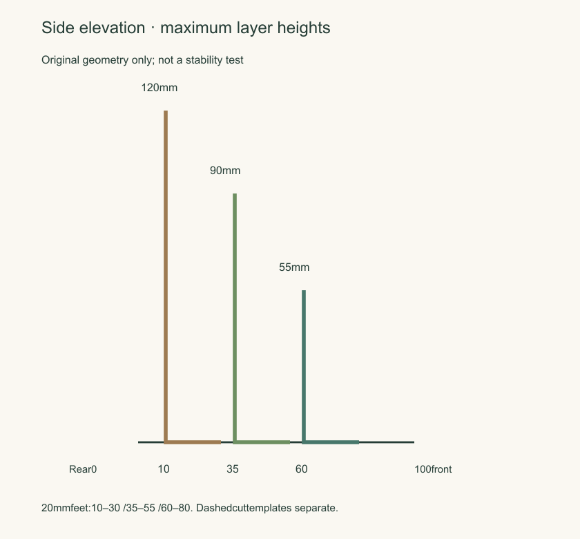
The three layers are each 180 mm wide. Their maximum visible heights are 120,90 and 55 mm. Add the 20 mm foot below each upright part, giving maximum cutting heights of 140,110 and 75 mm. These are bounding sizes, not instructions to cut three complete rectangles and ignore their upper contours.
Draw the mountain with its own coordinate origin
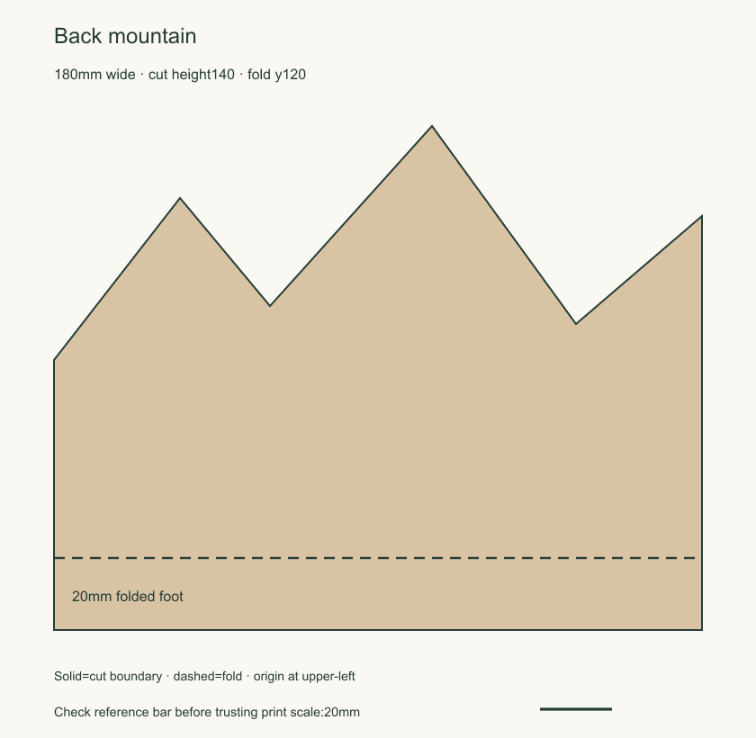
For the back layer, place a local origin at the upper-left corner of a 180-by 140 mm cutting envelope. Measure x to the right and y downward. Join these six upper-contour points in order with straight lines: (0,65), (35,20), (60,50), (105,0), (145,55), (180,25). The changing slopes create this authored mountain rather than a copied landscape.
From the last point, continue down to (180,140), across to (0,140), then back to (0,65) to close the outer cutting boundary. Draw a dashed fold from (0,120) to (180,120). The 20 mm band between y 120 and 140 is the foot. The highest peak at y 0 therefore stands 120 mm above the fold in the nominal upright view.
The templates include a 20 mm reference bar. If printing a diagram, measure that bar before trusting the scale; a page or browser can resize an image. Alternatively, redraw from the coordinates and check the 180 mm width directly. The displayed raster size does not establish a physical cut size.
Give the hill and riverbank separate envelopes
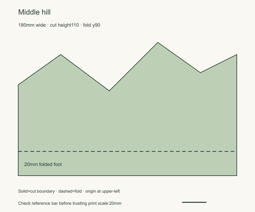
For the middle hill, use a new local origin in a 180-by 110 mm envelope. Its top points are (0,35), (35,10), (75,40), (115,0), (150,25), (180,10). Continue to (180,110), then (0,110), and return to the first point. Its fold runs across y 90, leaving the foot from y 90 to 110. Do not carry the mountain's y 120 fold into this shorter part.
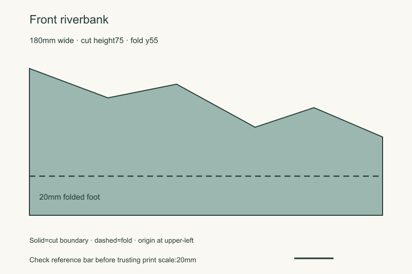
For the front riverbank, use another origin in a 180-by 75 mm envelope. Join (0,0), (40,15), (75,8), (115,30), (145,20), (180,35). Continue to (180,75), across to (0,75), then back to (0,0). Fold across y 55, leaving its foot from y 55 to 75.
Each contour is complete: an upper sequence, two ends and one bottom edge. The given y values describe a downward drawing coordinate, not the eventual height above the base. To recover that visible height at any contour point, subtract its y value from the layer's fold y. This explains why the mountain's point (105,0) is the highest, while the front bank's far-right point is only 20 mm above its fold.
Mark the base before attaching a foot
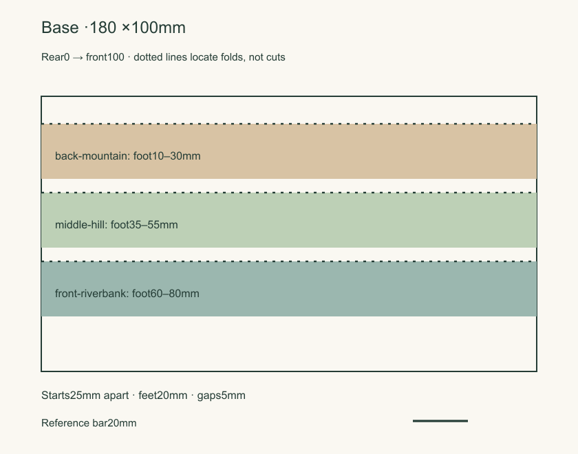
Prepare the separate 180-by 100 mm base. Let its depth coordinate run from the rear edge at 0 to the front edge at 100. All three layers span its full 180 mm width. Mark three placement lines parallel to that width, at depths 10,35 and 60.
The mountain's fold sits on depth 10 and its foot turns toward the front, occupying 10 through 30. The hill's fold sits at 35 and its foot occupies 35 through 55. The riverbank's fold sits at 60 and its foot occupies 60 through 80. The feet therefore do not overlap in this nominal plan.
The arithmetic is worth keeping visible: the fold starts are 25 mm apart; each foot is 20 mm deep; the clear gap between neighboring feet is 5 mm. There is a 10 mm rear margin before the first fold and 20 mm left at the front after the final foot. A 15 mm start spacing would overlap the feet and is not the spacing used here.
Keep the assembly order visible in the side view
First compare the three complete outlines while they are flat and verify the correct fold on each. Then form the feet so that all extend toward the same front direction. Arrange the mountain at the rear, hill in the middle and bank at the front on the marked base. The side elevation shows their maximum heights, not a prediction that every point on a silhouette reaches that height.
Check that each fold meets its own placement line and that no foot crosses the next line. If using adhesive to secure the feet, follow the actual material instructions and keep the marks visible until placement has been confirmed. The design supplies attachment areas; it cannot promise that an arbitrary thin sheet will stay upright or that an untested bond will hold.
If a chosen material curls, slumps or will not make the fold appropriately, stop and reconsider that material and support rather than treating the numerical plan as proof of stability. A flat arrangement can still show the three contours while those questions remain unresolved. Do not display an unstable assembly where it could interfere with ordinary desk use.
Compare the layers before adding detail
From the front, the shorter bank leaves room for the taller hill and mountain to appear above it. The contour variations determine where one edge interrupts another. Try that relationship in the dimensioned drawing before adding printed textures, tiny trees or extra layers. None is necessary to make the three-part depth proposal understandable.
The useful completed design is the set of three full contours, three separate fold feet and their checked base placement. It is not a photographed finished object or a claim about outdoor, wet or heated use. Keeping those limits clear lets the paper construction remain a concrete making project whose materials can be chosen and evaluated honestly.
Sources & further reading
Published sources for the details and examples discussed in this story.